Goodricke-Physics-Hub
This leg of the Current Broadcast Network carried the video and audio feeds from the studio through to the central distribution hub where it was distributed out to the various destinations on campus.
Structure
The cable route consists of a series of extensions added on at each major upheaval in YSTV's history to allow us to keep broadcasting via the existing infrastructure. It is therefore less than planned.
Behind the monitor rack in the control room is a piece of tag strip screwed to the cable duct, which has three XLR connectors coming off it. These are marked up as Network Audio, Derwent Send and Derwent Return. The last two are basically contribution circuits and re-patched as needed, whilst Network Audio should be fed with the balanced network audio signal. Video is carried on a standard BNC connector plugged in to patch box 6.
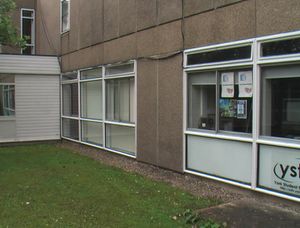
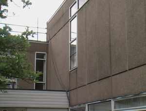
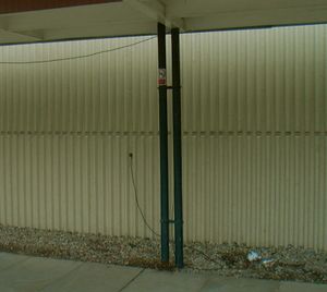
From the tag strip a 3-pair sheilded cable of the type used for the 1998 network and the 150m unbalanced video cable (originally made for Breaker 88) go through the window frame by the monitor rack, along the top of the G/045 windows and up over the room of the college nucleus. From here it wends it's way down along the covered walkway past the (old) Dining Hall and the bar to the "bus stop", then turns left past the cash machine towards the Physics and Electronics building. Just before the doors into this it goes through holes in the wall of the building to reach the attic room above P/X/002. There are in fact two separate holes. One above the walkway takes the audio cable and the coax return feed cables, and the other about 2 feet from the floor takes the network video cable, which has wondered off the side of the walkway with a cable tie round the walkway leg to keep it there. This cable then goes up the wall of P/X/002 and then across the ceiling to reach the attic.
Above P/X/002 in the attic there is a wall box with a white plate on it carrying two BNC connectors and four 1/4" jack sockets (someone in York - please take a photo and add it here). These are the ends of the old Rediffusion local contribution cables to P/S/016. Originally these would have taken individual camera feeds back to the studio and AV rack in P/S/016, but now they act as a pair of audio and video tie lines. The unbalanced video from Goodricke is plugged into the video lead (possibly via a video DA if we want to send video down to the concourse as well). The audio cable splits to three balanced jack connectors (with a common screen), one of which has the network audio on it. How these are plugged in will obviously change the function of the circuits from here onwards, however both sides are labelled, and this shouldn't need changing.
The video cable on this section, like most of the other local contribution cables, is a Belden braided foil screened type rather than standard RG59. This gives good shielding and so picture quality, but is very difficult to put a standard crimp connector onto successfully! The braid ends are also sharp, which can make the process painful. The audio cables are unshielded, with two grey and two blue cores in each black outer sheath. The 4 jack connectors wire up all 4 pairs (treating the two blue as a pair and so on) in two cables, without regard to phasing. If anyone ever tries stereo, beware! There is no screen connection to the jacks as the cables are unshielded.
These cables join the mass of other Rediffusion cables running down the wall, through the hole in the floor and into the cable duct in the room below. From here a 6" pipe is laid under the floor of the physics concourse (so I was told), which has a T off to the right near the porter's desk to reach the start of the physics spine corridor. Somewhere here the cables make it up and into the ceiling void above the corridor, where they run until they reach P/S/016.
In P/S/016 the audio cables are joined straight on to the 6-pair Rediffusion audio contribution cable which runs to the Hub (originally to LTC). The unbalanced video is fed into a line driver in order to drive one half of the shielded twisted pair Rediffusion video contribution cable to the Hub.
These contribution cables go back up into the ceiling void, and then back along the corridor to the concourse, and into the pipe under it, now taking the right turn by the porter's lodge to head through the building and out into the covered walkway towards Central Hall. This duct goes across the bridge (exactly how is unknown), then into the underground duct past the front of Central Hall, before coming back up to reach the Hub. This run consists of unbroken Rediffusion cabling.
Core Colours
This reflects the audio?Unverified or incomplete information wiring in place as of 2006. As all the joints are soldered or terminal blocked, it's unlikely to change, although the patching of the connectors may well do so.
| Circuit | Colour PX002<->Goodricke |
|---|---|
| Derwent Ret | White / Black pair |
| Derwent Send | Red / Black pair |
| Network Send | Green / Black pair |
| Usage (nominal) | Label in PX003 | Colour PX003<->PS016 | Colour PS016<->Hub |
|---|---|---|---|
| Derwent Ret | Derwent Return | Grey in 1st Cable | Yellow pair in 6-pair |
| Derwent Send | Derwent Comms | Blue in 1st Cable | Grey pair in 6-pair |
| Network Send | Net A1 | Grey in 2nd Cable | Blue pair in 6-pair |
| Unused | Net A2 | Blue in 2nd Cable | no circuit |
Demise
In 2011, the long-awaited construction of a new SU building on the site of the old dining room and bar resulted in the removal of a section of covered walkway connecting Physics and the now-James College building. The cabling running through this section was cut, severing the connection from G/046 to the rest of the network, and was eventually left coiled on the roof of the new building upon it's completion in June 2012. No attempt was made to reconnect the lines as the network was by then rarely used, with IP distribution becoming the norm. Cabling remains on the roof to this day.
In September 2016, the line coming into G/046 were cut in an effort to tidy up the control room cabling. The exterior cabling is still present.


