Distribution Network
Original Network
Whilst the University was being built during the late 60s and early 70s, the decision was taken that a closed-circuit television broadcast system would be a good idea. After an early experiment with VHF distribution and a daisy-chain contribution system that formed a giant ring, the contract was given to the Rediffusion company, whose main business was in distributing paid TV and radio services to householders over wired networks.
A closed circuit system of Audio Visual (AV) distribution and contribution was installed, along the lines of a small urban area commercial system, but with a greater provision for sending video back from the various parts of the university to be broadcast. The system allowed up to 4 channels to be conveyed around campus on a multipair pair cable, with each channel dedicated to a separate pair. Further pairs in the cable allowed for up to 9 channels, 5 of them video and the other four audio-only. Video channels carried both the audio and video signals on a single pair. An equipment room LTC (adjacent to Central Hall) acted as the transmission hub. For transmission, the video was modulated onto a carrier at 4.5MHz (405-line B+W channels) or 10.7MHz (625-line colour-capable channels) and the audio (at baseband) amplified. Audio-only channels were fed via power amplifiers so that outlets could use passive loudspeakers without further amplification, on the same basis as 100V-line PA systems. The transmission equipment and televisions were supplied by Rediffusion VisionUnverified or incomplete information. This method of cable based AV distribution was used in a number of towns in the UK, however it had reached the end of it's technological lifetime by the end of the 1980's. The system installed at the University of York was originally black and white (with a mixture of 405-line (BBC1) and 625-line (BBC2) channels and was upgraded to support colour in the 1980s.
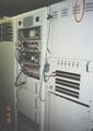
Rediffusion racks in LTC
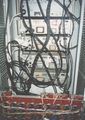
Cable entry and exit in LTC
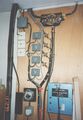
Video modulators in LTC


Installed alongside the distribution network was an AV contribution network. Located somewhere within most colleges was an AV rack. This was fed from a collection of contribution points located in seminar or lecture rooms in the college using coax for video and twisted pair for audio. Within the rack, the video could be patched in to a video line driver transmitter which was linked via twisted pair to a corresponding receiver over in LTC. The audio was directly patched as this was already balanced line. Wentworth was the last of the original 6 colleges to be built and no system of AV contribution was installed, presumably as a cost saving measure. Langwith and Derwent had been built before the Rediffusion system was commissioned, so although a distribution network was installed, and possibly a link from the old ring system to the new one, no Rediffusion contribution system was installed.
The contribution/distribution system was quite advanced in it's day since it would have been possible to do point to multi-point lectures and video conference across campus. However, it is not known if it every was ever utilised beyond retransmission of BBC1/BBC2/ITV and contribution/distribution of YSTV.
The passing of the years had taken its toll on the system. By 1994, various colleges/buildings had been remodelled, leading to removal of the AV racks or cutting of contribution/distribution cables. At the time YSTV moved into G/046, the contribution cable from Goodricke back to LTC had suffered a break. This lead to the contribution point in P/X/002 being pressed back into service. From here it fed back to the AV rack in P/S/016 before being sent to LTC. At the time, YSTV could be seen in Derwent, Langwith, Alcuin, Vanbrugh and Goodricke. Wentworth distribution had been lost sometime between 1993-94. The distribution system suffered from having to use televisions that could receive the Rediffusion signal. This made replacing them difficult, since Rediffusion had pretty much dissapeared and the transmission system was technologically obsolete. The proximity of the Goodricke snack bar to G/046, allowed audio and video to be fed at baseband to a normal television via a SCART socket. The remaining televisions soldiered on, and when required were repaired by using parts from any spares that could cannibalised from the spares from the garage in Wentworth. Despite best efforts, picture quality was suffering, colour would turn to black and white and then back or various interference patterns could be seen on the screen.
Vanbrugh Upgrade
During the summer holidays of 1995, Owain Davies visited the station and stumbled across a flyer from Maxim highlighting their MAX435/MAX436 video balanced line drivers and receivers.
At this point, he did not know if he was return to York or not, however he took the flyer away to read at home. He had come across the benefits of balanced line audio ealier on in his Electronics degree and seen it in practice at YSTV where it was used to convey microphone signals down incredibly long pieces of dirty EM infiltrated cable and be amplified at the other end, resulting in crystal clear clarity. The example circuit diagram seemed a remarkable simple solution, just one ic for transmitter and one for the receiver. He returned to York in September of 1995, however he was not due to start his tenancy on a house in Osbaldwick for a week or so and therefore had temporary accommodation in Fairfax House. It was here that the prototype transmitter and receiver were constructed. Trials of the units were performed in the studio of G/046 using twisted pair audio cable. This soon ran out with the units managing to successfully convey the signal, so he resorted any scrap of telephone cable, mains cable, or any cable he could lay his hands on. The signal did eventually deteriate, usually with the picture going black and white due to a dissapearing colour burst (in fact he was amazed by how much the colour burst could reduce in amplitude and colour in the picture remain). He experimented with different resistor and capacitor networks on the feedback loop of the receiver amplifier in an attempt to equalise the high frequency loss of the cable. It was demonstrated to various members of the station using two monitors, one showing before transmission and the other reception with a sea of cable of the floor. The subject under test was given the challenge to determine which monitor was showing the picture that had gone down the various different types of cable. At this point it was decided to inform AV of the idea, since they were the other stakeholder in the network. A meeting was held and they seemed quite interested in the idea and they offered to loanUnverified or incomplete information the electrical fix installation plans for the University. Their collection was quite comprehensive covering most of the University's buildings, from the colleges down to the VC's bungalow. On these plans were marked the locations of the various contribution points, AV racks and routing information of the cables linking the two.
Owain had found in LTC the composite output from the contribution feed from Physics. The picture was in good condition, meaning the interference problems were occuring on the distribution side of the network only. Armed with the knowledge from the plans, LTC began to make more sense. Three things came out from this visit
- LTC could act as the distribution for the new network since the composite was good.
- Since the composite was good, a lot of the wiring must be good and therefore could be reused.
Audio driver used SSM2142/SSM2141.