Station Video Mux: Difference between revisions
Mikechislett (talk | contribs) |
Mikechislett (talk | contribs) (→Today) |
||
| Line 28: | Line 28: | ||
In 2006 the original PIC within the controller was replaced with a PIC18F2455. This was the first step towards giving [[Spider and SchedSeven]] control of the Mux, although currently the USB side of the firmware is still under development. | In 2006 the original PIC within the controller was replaced with a PIC18F2455. This was the first step towards giving [[Spider and SchedSeven]] control of the Mux, although currently the USB side of the firmware is still under development. | ||
After a dramatic hardware failure at Roses 2011 (late summer), the Mux controller begin to get 'picky' about if it liked working on certain days of the week. It was later discovered that some rather large capacitance had bridged across a pair of control lines, making the system purport to work (the Main unit has no way of communicating back to the controller). With no documentation available, it was decided that replacing the controller with a serial interface was the way to go. By 2012, the new control system was implanted into the main unit, making the old external box redundant. As of March 2012, the machine now conforms to the YVP protocol. Several easter eggs have been programmed into the device - please don't go looking for them during a live show... | |||
---- | ---- | ||
More [[YSTV Technicals]] | More [[YSTV Technicals]] | ||
Revision as of 11:23, 6 August 2012
Breaker 88
The mammouth broadcast of Breaker 88 was responsible for several new pieces of YSTV equipment being designed and built, a sync pulse generator (SPG) in a 2U rack, and a video multiplexor.
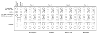
The video mux had 4 buses: Auxilliary, Tape, Record, Network. By the mid 1990's various bits of the original circuitry had failed and no replacement parts were obtainable, so the mux had some rotting limbs amputated to reduce it to only 3 buses. A separate 1U mux switched network video under the control of BBC Schedula.
Motivation to design a new video mux was severalfold:
- Only 3 terrestrial tuners remained from the original Rediffusion system, these had to be manually changed over by the Scheduling Manager to match the schedule depending on which of the 5 terrestrial channels were required, and some of these buttons were jammed too
- An explosion of video equipment within the larger G/046 station meant all of the remaining working inputs were now in use
- The black controller box would 'crash' occasionally when the state machine inside made out of logic chips got stuck
- A desire to simplify the video setup so that any video source could be routed to and from anywhere
32 x 4 replacement
A replacement mux was first explored in 1997 by Rob Sprowson, though not built straight away due to other pressing projects and budget constraints. Instead the parts were accumulated slowly and design work done during the university holidays. Finally in April 2001 the new layout was sent off to be made, and finally the parts could be pieced together.
An increase was made to 32 inputs and 4 outputs, along with controller box.
It included two NICAM stereo terrestrial tuners from Display Electronics which could be retuned under computer control, this was key to the scheduling system and was also intended to make use of the recently upgraded AV network which was stereo capable.
The new mux was briefly installed for a weekend for testing in 2002Unverified or incomplete information and later withdrawn for minor hardware alterations - it was carried back to Cambridge by train, which included a brief section sliding round in the back of a coach as a derailment had meant trains had to skip part of the journey to Peterborough, making it the most travelled mux in history.
All the parts were sourced as free samples from Maxim under various psuedonyms since the MAX458 crosspoints were actually worth about £40 each.
To avoid the obsolescence problem that the Breaker 88 unit suffered, there were two muxes. One live, then a spare circuit board and set of 7 chips were in storage in case of failure, the controller made using a cheap reprogrammable micro controller. Some 885 lines of assembler code are all that were required in the micro to perform all of its control functions.
Today
The outputs originally drove 8 copies of each bus to avoid the need for seperate distribution amplifiers, however in a heavily loaded system some crosstalk was observed. This was misdiagnosed as due to electric fields (!) and the integrated amplifiers chopped out, despite the MAX497 buffers being socketted. It is believed simply increasing the decoupling to the power supply would have resolved the problem and left the unit at its full specification.
In 2006 the original PIC within the controller was replaced with a PIC18F2455. This was the first step towards giving Spider and SchedSeven control of the Mux, although currently the USB side of the firmware is still under development.
After a dramatic hardware failure at Roses 2011 (late summer), the Mux controller begin to get 'picky' about if it liked working on certain days of the week. It was later discovered that some rather large capacitance had bridged across a pair of control lines, making the system purport to work (the Main unit has no way of communicating back to the controller). With no documentation available, it was decided that replacing the controller with a serial interface was the way to go. By 2012, the new control system was implanted into the main unit, making the old external box redundant. As of March 2012, the machine now conforms to the YVP protocol. Several easter eggs have been programmed into the device - please don't go looking for them during a live show...
More YSTV Technicals
